
|
www.riscos.com Technical Support: |
Any of the colours which are available in a given mode may be 'interwoven' to give a tremendous range of colour patterns. When using modes with a limited number of colours, for example any of the four-colour modes, this feature may be used to extend the colours available, since combining similar colours produces further shades which look like pure colours. Alternatively, contrasting colours may be used to give checks, wavy lines, and so on.
Default patterns are set up for you as follows:
| Mode(s) | Pattern | Colour |
|---|---|---|
| 0 | 1 | Dark grey |
| 2 | Grey | |
| 3 | Light grey | |
| 4 | Hatching | |
| 4,25 | 1 | Dark grey |
| 2 | Grey | |
| 3 | Light grey | |
| 4 | Hatching | |
| 1,5,8,26 | 1 | Red-orange |
| 2 | Orange | |
| 3 | Yellow-orange | |
| 4 | Cream | |
| 2,9,12,27 | 1 | Orange |
| 2 | Pink | |
| 3 | Yellow-green | |
| 4 | Cream | |
| 13,15,28 | 1 | White-grey stripes |
| 2 | Black-grey stripes | |
| 3 | Green-black stripes | |
| 4 | Pink-white stripes |
To use these patterns you issue a GCOL with a plot action which depends on the pattern desired. In general, to use pattern n, the GCOL command should be
GCOL n*16+action, col
where action is the plotting action you want to use with the pattern (for example 0 for store, 1 for OR etc, as described earlier), and col is 0 if you want to set the foreground colour as a pattern or 128 for a background pattern. The parameter n is in the range 1 to 4 for the normal patterns, or 5 for a large pattern which is formed by placing patterns 1 to 4 next to each other.
All the shapes which have been described above can be plotted using these colour patterns. A pattern may be selected using GCOL. The first parameter to GCOL affects the plotting action as was seen earlier in the Screen modes chapter. Patterns can be used in future plots by using values in the following ranges:
| 16-31 | Pattern 1 |
| 32-47 | Pattern 2 |
| 48-63 | Pattern 3 |
| 64-79 | Pattern 4 |
Try the following:
10 MODE 9
20 GCOL 16,0
30 MOVE 100,100
40 MOVE 800,800
50 PLOT &55,700,200
or
10 MODE 1
20 GCOL 32,0
30 MOVE 640,512
40 PLOT &9D,740,512
It is possible to plot lines using these colour patterns in a similar manner, but the effects may be rather strange. Consider, for example, a line drawn at 45 degrees in mode one. If the pattern being used were alternate black and white pixels, then this line would be drawn either in all white or all black, the latter not being visible on a black background.
You may define your own colour patterns using VDU commands as follows:
VDU 23,2,n1,n2,n3,n4,n5,n6,n7,n8 defines GCOL 16,0 i.e. pattern 1
VDU 23,3,n1,n2,n3,n4,n5,n6,n7,n8 defines GCOL 32,0 i.e. pattern 2
VDU 23,4,n1,n2,n3,n4,n5,n6,n7,n8 defines GCOL 48,0 i.e. pattern 3
VDU 23,5,n1,n2,n3,n4,n5,n6,n7,n8 defines GCOL 64,0 i.e. pattern 4
The pattern produced by a set of parameters depends upon which pattern mode is being used. There are two modes available, one where the parameters are interpreted in the same manner as on a BBC Master 128 and another simpler method used by this machine only. The default is the BBC Master 128 mode. To change to native mode type
VDU 23,17,4,1|
To revert back again to the Master mode type
VDU 23,17,4|
Note: the | character denotes a floating point indirection operator. See the chapter entitled Accessing memory locations for more information.
The pattern fill works with blocks of pixels. The size of these blocks depends on the number of colours available in the mode:
| Colours | Horizontal pixels | Vertical pixels |
|---|---|---|
| 2 | 8 | 8 |
| 4 | 4 | 8 |
| 16 | 2 | 8 |
| 256 | 1 | 8 |
In all cases, each pixel may be assigned a colour independently of the others. Each parameter of the VDU command corresponds to a row in the pixel block. The first parameter contains the value of the top row, the second the value of the second row, and so on. The way the value of the parameter is interpreted depends on the mode being used.
In native mode the bits of the parameter are used in a straightforward manner to give the colour of the pixels.
Each bit of the parameter is assigned to a pixel, the least significant bit applying to the pixel on the left, i.e. the pixels appear on the screen in the opposite order to which the bits are written down on paper. For example, to set a row of the pattern as follows:
| black | white | white | white | black | black | black | white |
| %0 | %1 | %1 | %1 | %0 | %0 | %0 | %1 |
the value required is 142 (%10001110).
Each pair of bits of the parameter is assigned to a pixel, the least significant pair applying to the pixel on the left. For example, to set a row of the pattern as follows:
| yellow | red | white | yellow |
| %10 | %01 | %11 | %10 |
the value required is 182 (%10110110).
Each set of four bits of the parameter is assigned to a pixel, the least significant set applying to the pixel on the left. For example, to set a row of the pattern as follows:
| green | white |
| %0010 | %0111 |
the value required is 114 (%01110010).
The value of the parameter defines the colour assigned to the pixel directly. Patterns in these cases are more complex since they involve interleaving the bits from the colour to obtain the parameter value.
In BBC Master 128 mode, the bits of the parameter are used in the following manner to give the colour of the pixels:
This is the easiest case to understand. Each pixel in the block corresponds to one bit of the parameter, the least significant bit applying to the pixel on the right, so pixels on the screen appear in the same order as the bits are written down on paper. For example, to set a row of the pattern as follows:
| black | white | white | white | black | black | black | white |
| %0 | %1 | %1 | %1 | %0 | %0 | %0 | %1 |
the value required is 113 (%01110001).
Defining a pattern in a two-colour mode is similar to setting up a user-defined character.
In four-colour modes each colour is defined using two bits as follows:
| yellow (%10) red (%01) white (%11) yellow (%10) | |||||||||
| bit | 7 | 6 | 5 | 4 | 3 | 2 | 1 | 0 | |
| 1 | 0 | 10 (yellow) | |||||||
| 0 | 1 | 01 (red) | |||||||
| 1 | 1 | 11 (white) | |||||||
| 1 | 0 | 10 (yellow) | |||||||
| 1 | 0 | 1 | 1 | 0 | 1 | 1 | 0 | ||
|---|---|---|---|---|---|---|---|---|---|
The value required is 182 (%10110110).
In 16-colour modes the situation is different again. There are just two pixels in a row, four bits of the parameter being used to hold the value of each colour. However, it is not the case that the left-most four bits correspond to the first colour and the right-most four bits to the other. Instead, the bits of each are interleaved, as shown:
| green (%0010) white (%0111) | |||||||||
| bit | 7 | 6 | 5 | 4 | 3 | 2 | 1 | 0 | |
| 0 | 0 | 1 | 0 | 0010 (green) | |||||
| 0 | 1 | 1 | 1 | 0111 (white) | |||||
| 0 | 0 | 0 | 1 | 1 | 1 | 0 | 1 | ||
|---|---|---|---|---|---|---|---|---|---|
and the value required is 29 (%00011101).
To get the colours the other way around different numbers are required:
| white (%0111) green (%0010) | |||||||||
| bit | 7 | 6 | 5 | 4 | 3 | 2 | 1 | 0 | |
|---|---|---|---|---|---|---|---|---|---|
| 0 | 1 | 1 | 1 | 0111 (white) | |||||
| 0 | 0 | 1 | 0 | 0010 (green) | |||||
| 0 | 0 | 1 | 0 | 1 | 1 | 1 | 0 | ||
and the value required is 46 (%00101110).
Thus a cross-hatch pattern of alternate white and green pixels can be defined:
VDU 23,2,29,46,29,46,29,46,29,46
Giant patterns can be set up which take all four of the separate patterns and place them side by side, giving an overall pixel size as shown below:
| Colours | Horizontal pixels | Vertical pixels |
|---|---|---|
| 2 | 32 | 8 |
| 4 | 16 | 8 |
| 16 | 8 | 8 |
| 256 | 4 | 8 |
To produce a giant pattern in this way, the first parameter given to GCOL should be in the range 80 to 95.
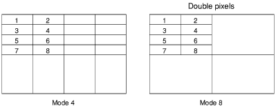
Often the most effective way of using the pattern fills is for simple cross-hatch patterns. If you want to use this sort of colour pattern, a simpler way of defining it is available. In this method, just a small block of eight pixels is defined which is used to form the normal-sized block.
The eight pixel colours in the following diagram are set up using
VDU 23,2,n1,n2,n3,n4,n5,n6,n7,n8
where n1 to n8 correspond to the actual colours to be used.

The numbers are given in the following order:
This section is concerned with how to fill the inside of any closed region, however awkward the shape. The method used is flood-filling; with this you can start off at any point within the boundaries of the shape. The whole shape is then filled at once.
Note that flood-filling is not compatible with BASIC programs written under the window manager environment (described in the Window managed programs) section.
This can be used on shapes which are in the current background colour and bordered by non-background colours. The shape is filled with the current foreground colour.
To use this flood-fill method, type, for example:
This starts filling from the point (640,512): the middle of the screen. If this point is in a non-background colour then it returns immediately. Otherwise it fills in all directions until it reaches either a non-background colour or the edge of the screen.
Flood-fills may be performed using either pure colours or colour patterns. Note that if you wish to colour in a shape it must be totally enclosed by a solid border. If there is a gap anywhere then the colour 'leaks' out into other regions.
Whereas the previous flood-fill filled a shape currently in the background colour, this one fills a shape currently in any colour except the present foreground one, with the present foreground colour. This is performed by a PLOT command with plot codes &88 to &8F.
For example:
PLOT &8D,640,512
Flood-filling will only succeed when the region being filled does not already contain any pixels in the colour being used. For example, if you are attempting a flood to non-background when the background colour is black, you should not try to flood in black or in a pattern which contains black pixels.
Using RECTANGLE TO AND RECTANGLE FILL TO_ YOU CAN PICK UP A RECTANGULAR AREA OF THE SCREEN AND EITHER MAKE A COPY OF IT ELSEWHERE ON THE SCREEN OR move it to another position, replacing it with a block of the background colour.
For example:
RECTANGLE FILL 400,600,60,80 TO 700,580
This marks out the source rectangle as having one corner at co-ordinates (400,600), a width of 60 and a height of 80. It then moves this rectangular area so that the bottom left of it is at the co-ordinates (700,580). The old area is replaced by background.
The new position can overlap with the rectangular area, as in the example above, and the expected result is still obtained.
The rectangle move and copy commands may also be expressed in terms of PLOT codes. The relevant range of codes is &B8 to &BF: first move to two points which denote the bottom left and top right of the rectangle to be copied or moved; then plot, using one of the range of codes described above, to the bottom left corner of the destination rectangle. The meanings of the plot codes are as follows:
| &B8 | Move relative (no copy/move operation) |
| &B9 | Relative rectangle move |
| &BA | Relative rectangle copy |
| &BB | Relative rectangle copy |
| &BC | Move absolute (no copy/move operation) |
| &BD | Absolute rectangle move |
| &BE | Absolute rectangle copy |
| &BF | Absolute rectangle copy |
The rectangle move operations erase the source rectangle, whereas the copy operations leave it intact. So, the RECTANGLE FILL TO example above could also be expressed as:
MOVE 400,600
MOVE BY 60,80
PLOT &BD,700,580
The graphics used by Draw use the Draw module. This is outside the scope of this manual, but is described in the Programmer's Reference Manual.